

The purpose of this post is to show how to use multi-threading to parallelize data processing with data transfer from pageable to page-locked memory. I was motivated to examine this issue while looking at the effect of the pin_memory flag in PyTorch’s dataloader. Let me provide some background information first.
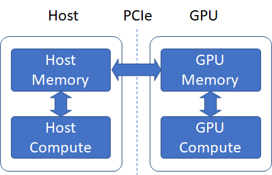
Data loading is the first step in any machine learning (ML) application. During data loading on a GPU enabled machine, a batch of data is loaded from the disk into main memory and then transferred to the GPU, where compute intensive tasks such as forward pass, backward pass (calculation of gradients) and parameter updates are carried out. These tasks are highly parallel, i.e., multiple calculations can proceed at the same time and thus implementation on a massively parallel compute platform such as a GPU is very efficient.
Table of Contents
Host-GPU Interconnect
GPUs are usually connected to the motherboard over a PCIe connection and data from the main (host) memory must be transferred to the GPU memory over this PCIe link. What is the expected bandwidth of this link? To answer this question, lets look at some basic info about PCIe links.
PCIe link performance is characterized by transfer rate and encoding scheme. Transfer rate refers to the total number of bits transmitted, including the data and overhead bits. Encoding scheme is the ratio of data bits to the total number of bits. There are many revisions of PCIe varying in transfer rate and encoding scheme. The table below shows the per lane transfer rate and throughput for PCIe 1.0, 2.0 and 3.0. For more information, see the PCIe wikipedia article.
|
|
Encoding | Transfer Rate( bits/sec) | Throughput (MB/sec) |
|
PCI 1.0 |
8b/10b | 2.5 Gb/sec |
8/10*2.5/8 = 250 MB/sec |
|
PCI 2.0 |
8b/10b | 5 Gb/sec |
8/10*5/8 = 500 MB/sec |
| PCI 3.0 | 128b/130b | 8 Gb/sec |
128/130*8/8 = 984.5MB/sec |
Physical PCIe links may contain from one to 32 lanes. Lane counts are written with an “x” prefix (for example, “x8” represents an eight-lane card or slot), with x16 being the largest size in common use. The lane count together with the throughput per lane gives us the expected data transfer bandwidth. For example, an x16 PCIe 3.0 connection is expected to have a maximum bandwidth of 16*984.5=15.7 GB/sec.
Identifying PCIe version and number of lanes on your system
To find out the PCIe version and number of lanes for the GPU interconnect on my system (Windows 10 x64, with a Nvidia 1080 Ti GPU), I used this Python code that uses the pycuda CUDA-Python wrapper to query CUDA device info.
|
1 2 3 4 5 6 7 8 |
driver_ver = cuda.get_version() print("CUDA Driver Version: {0}.{1}.{2}".format(driver_ver[0], driver_ver[1], driver_ver[2])) num_cuda_devices = cuda.Device.count() for i in range(0, num_cuda_devices): dev = cuda.Device(i) pci_bus_id = dev.pci_bus_id() dev_name = dev.name() print("device id: {0}, device name: {1}, bus_id: {2}".format(i, dev_name, pci_bus_id)) |
The pci_bus_id gives you the id of the bus used by GPUs on your system. From the pci_bus_id, you can obtain the number of lanes as follows:
Linux
Run the linux command lspci as shown below
|
1 |
lspci -vv |grep 04:00.0 -C 100 |
Replace the 04:00.0 with the bus id on your system. Look for Width in “LnkCap” in the resulting output.
Windows
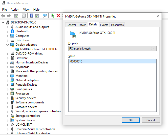
Getting this info was surprisingly tricky on Windows. I tried installing the Windows Driver Kit and using the “devcon” utility that comes with it, however that was not easy or intuitive and I didn’t want to go down that rabbit hole. I ended up using the windows device manager as follows:
windows device manager -> Display adapters-> <right click “properties” on GPU name> -> in the “property” drop down in the dialog box, “PCI max link speed” gives the PCIe version and “PCI max link width” gives the number of lanes (in hex).
Host memory types
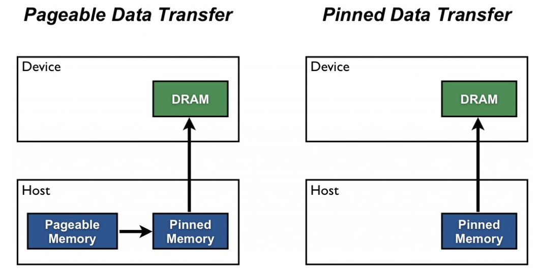
Turning to host memory, there are are two main categories – pageable (or “un-pinned”) and page-locked (or “pinned”) memory. When you allocate memory using malloc in a C program, the allocation is done in pageable memory. The GPU cannot access data directly from pageable host memory, so when a data transfer from pageable host memory to device memory is invoked, the CUDA driver first allocates a temporary pinned host array, copies the host data to the pinned array, and then transfers the data from the pinned array to device memory, as illustrated below (see this page for more info)
Performance of host-to-device transfer from pinned and un-pinned memory
It is expected that data transfer from pinned memory to device will have a higher bandwidth than transfer from un-pinned memory. To verify this, I wrote a python script (see appendix) to test the host-to-device (h2d) data transfer BandWidth (BW) when the data is located in pageable vs. page-locked memory. The script uses the pycuda library that exposes low-level CUDA API in Python. The results are shown in the table below for 5 data sizes.
|
Data Size (MB) |
20 | 40 | 80 | 120 | 160 |
|
Transfer BW (page-locked) (GB) |
11.36 | 11.44 | 12.02 | 12.09 |
12.13 |
| Transfer BW (pageable) (GB) | 5.06 | 5.31 | 5.39 | 5.35 |
5.04 |
As expected, the transfer bandwidth from page-locked memory is much closer to the expected bandwidth on my system.
The figure below shows a plot of the two types of transfer involved:
- h2d transfer (no pinning): In this case, data is copied from pageable memory to the GPU host memory. The CUDA driver takes care of copying the data to page-locked memory
- h2d transfer (with pinning): In this case, data is allocated in pageable memory and explicitly copied to page-locked memory using the register_host_memory function in pycuda. This transfer time (h2h transfer time) is shown in the blue plot. Then, the data in page-locked memory is copied to the GPU. This transfer time is shown in the red plot. The total time is the sum of the two and is shown in the black plot
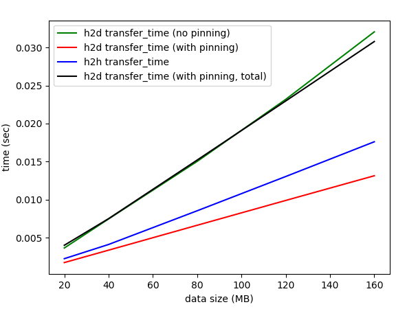
As expected, the two transfer times (green plot and the black plot) are nearly identical. This is because for h2d transfer from pageable memory, the CUDA driver is internally performing the transfer from pageable to page-locked memory.
We see that transferring data from unpinned to pinned memory is an expensive operation. Thus, it is clear that transfer from page locked memory is more efficient only if either the data can be allocated directly in page-locked memory or if the data processing on the GPU can be parallelized with the data transfer so that the data transfer latency is partly or completely hidden. CUDA provides APIs such as cudaMallocHost() to implement the first method.
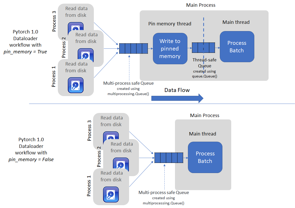
Dataloader in PyTorch 1.0
PyTorch’s dataloader takes the second approach. It uses multiple processes to load batch data from the disk into pageable memory and then spins up a separate thread to transfer loaded data to pinned memory (if the pin_memory flag = True). If not, the data loaded by the multiple processes is returned directly when enumerate or next(iter) is called by the user (see code for the imagenet example in PyTorch docs). The figure below shows a schematic of the two options.
Threaded data transfer experiment
I wrote a python script (see appendix) that implements a simple threaded loader to parallelize copy to page locked memory task with data processing. The script copies 160MB of data 100 times using three methods:
- Data is allocated in pageable memory and copied to the GPU using pycuda memcpy_htod() function on the main thread
- Data is allocated in pageable memory, copied explicitly to page-locked memory using pycuda PageLockedMemoryPool APIs and then copied to the GPU on the main thread
- A separate thread is used to perform copy to page-locked memory
The data process time is simulated by adding a sleep of 400 ms, which is comparable to the backprop time for Resnet 50 on a 1080Ti GPU for a batch size of 64.
The total processing times for the three methods are shown in the table below.
|
|
H2D (pageable) | H2D (page-locked) |
H2D (page-locked, threaded) |
| Total Processing Time (sec) (100 Runs) | 7.90 | 7.92 |
4.92 |
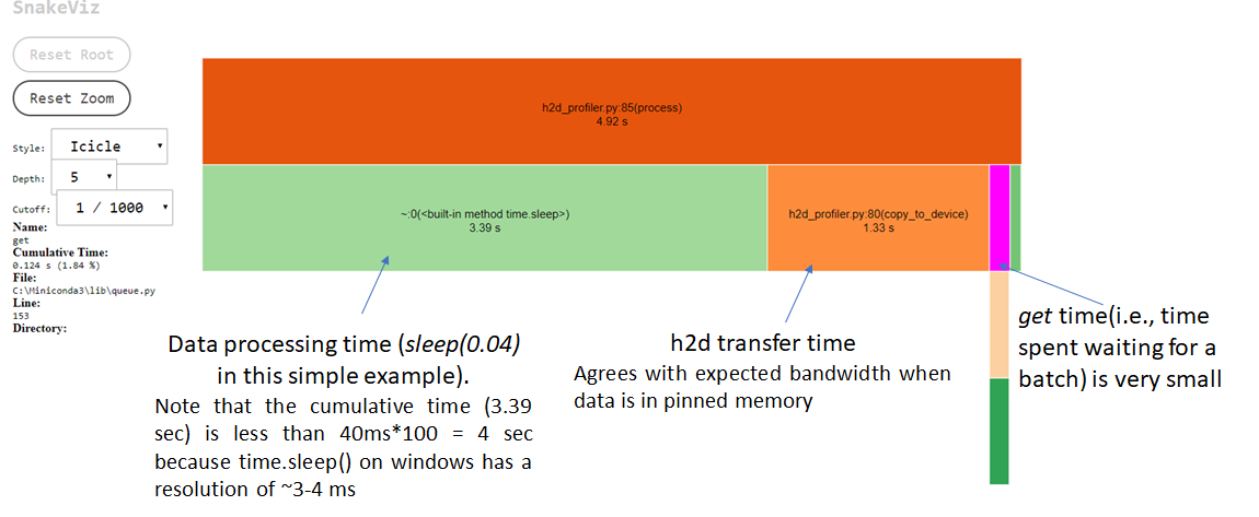
The threaded option is able to almost completely hide the data transfer latency. The total execution time is now dominated by the process time (sleep of 400*100 = 4 sec). We can also see this by profiling the code using cProfile and visualizing the result using snakeviz. Note that the actual cumulative sleep time is not exactly 4 sec because the resolution of the time.sleep() function on Windows is ~3-4 ms.
Incidentally, it is not easy to profile multiple threads in Python. cProfile works well for the main thread, but doesn’t give information about what’s happening with other threads. I also played around with Intel vtunes, but didn’t have much luck. If you know of good profiling tools for multi-threaded Python apps, let me know!
Conclusion
To conclude, in this post we looked at some basic information about PCIe links that helps you determine the expected data transfer bandwidth and considered an example that shows data transfer from pinned to device memory is much more efficient than transfer from un-pinned memory but unpinned-pinned memory transfer is an expensive operation in itself. We then examined how multi-threading can be used to perform unpinned-pinned memory transfer concurrently with host-to-device data transfer and data processing on device. Given a sufficiently large processing time, this can almost completely hide the latency of the data transfer.
Hope you found this useful. Please leave a comment if you did!
Appendix
Code for transfer BW performance comparison
|
1 2 3 4 5 6 7 8 9 10 11 12 13 14 15 16 17 18 19 20 21 22 23 24 25 26 27 28 29 30 31 32 33 34 35 36 37 38 39 40 41 42 43 44 45 46 47 48 49 50 51 52 53 54 55 56 57 58 59 60 61 62 63 64 65 66 67 68 69 70 71 72 73 74 75 76 77 78 79 80 81 82 83 84 85 86 87 88 89 90 91 92 93 94 95 96 97 98 99 100 101 102 103 104 105 106 107 108 109 110 111 112 113 114 115 116 117 118 119 120 121 122 123 124 125 126 |
import pycuda.driver as cuda from pycuda.tools import PageLockedMemoryPool import numpy as np import time import ctypes import pdb from queue import Queue from threading import Thread from pycuda.tools import make_default_context import matplotlib.pyplot as plt import threading # Initialize CUDA cuda.init() global ctx ctx = make_default_context() # will initialize the first device it finds dev = ctx.get_device() def _finish_up(): global ctx ctx.pop() ctx = None from pycuda.tools import clear_context_caches clear_context_caches() import atexit atexit.register(_finish_up) num_elems = [5000000, 10000000, 20000000, 30000000, 40000000] # prints pci_bus_id, device name and device id for installed GPUs. You can run the Linux lspci command on the bus_id to # obtain information about the number of PCIe lanes on that bus. This will give you the expected bandwidth def print_device_info(): driver_ver = cuda.get_version() print("CUDA Driver Version: {0}.{1}.{2}".format(driver_ver[0], driver_ver[1], driver_ver[2])) num_cuda_devices = cuda.Device.count() for i in range(0, num_cuda_devices): dev = cuda.Device(i) pci_bus_id = dev.pci_bus_id() dev_name = dev.name() print("device id: {0}, device name: {1}, bus_id: {2}".format(i, dev_name, pci_bus_id)) # Helper function to copy src array to destination using ctypes memmove def copy_np_to_pinned_memory(src, dest): src_ = src.ctypes.data_as(ctypes.POINTER(ctypes.c_float)) dest_ = dest.ctypes.data_as(ctypes.POINTER(ctypes.c_float)) sz = src.size * ctypes.sizeof(ctypes.c_float) ctypes.memmove(dest_, src_, sz) # This function measures the time taken to transfer data from host-to-device (h2d) when: # 1. source is in unpinned (pagaeable) memory # 2. source is in pinned memory. In this case, we also measure time taken to transfer data # from unpinned to pinned memory. # Times are measured for different data sizes and plotted. Data transfer bandwidth is also calculated from # the transfer times. def compare_performance(): # a quick warm up.. n = 25000000 a = np.random.randn(n).astype(np.float32) # allocate space on GPU mem_gpu = cuda.mem_alloc(a.nbytes) cuda.memcpy_htod(mem_gpu, a) # free space on GPU mem_gpu.free() h2d_nopin = [] h2d_nopin_bw = [] # measure timing without pinning for n in num_elems: # the data to be transferred a = np.random.randn(n).astype(np.float32) # allocate space on GPU mem_gpu = cuda.mem_alloc(a.nbytes) # only measure h2d transfer time start = time.perf_counter() cuda.memcpy_htod(mem_gpu, a) te = time.perf_counter() - start #te: time elapsed h2d_nopin.append(te) h2d_nopin_bw.append(a.nbytes/(10**9 * (te))) # convert to a bandwidth # free space on GPU mem_gpu.free() # now do pinning and measure time to pin and time to transfer h2h_pinned = [] # records the transfer time from unpinned -> pinned memory h2d_pin = [] # records the host to device transfer time with data in pinned memory. h2d_pin_total = [] # records the total (sum of the previous two) h2d_pin_bw = [] #h2d_pin, converted to a bandwidth (GB/sec) for i, n in enumerate(num_elems): a = np.random.randn(n).astype(np.float32) # allocate space on GPU mem_gpu = cuda.mem_alloc(a.nbytes) # allocate page locked memory a_pin = cuda.register_host_memory(a) # copy data from np array to pinned memory and measure transfer time start = time.perf_counter() copy_np_to_pinned_memory(a, a_pin) te = time.perf_counter() - start # te: time elapsed h2h_pinned.append(te) # measure h2d transfer time start = time.perf_counter() cuda.memcpy_htod(mem_gpu, a_pin) te = time.perf_counter() - start #te: time elapsed h2d_pin.append(te) h2d_pin_bw.append(a.nbytes / (10**9 * te)) h2d_pin_total.append(h2d_pin[i] + h2h_pinned[i]) # free allocated pinned memory a_pin.base.unregister() # free space on GPU mem_gpu.free() fig = plt.figure() num_elems_mb = [x*4/10**6 for x in num_elems] plt.plot(num_elems_mb, h2d_nopin, 'g', label='h2d transfer_time (no pinning)') plt.plot(num_elems_mb, h2d_pin, 'r', label='h2d transfer_time (with pinning)') plt.plot(num_elems_mb, h2h_pinned, 'b', label='h2h transfer_time') plt.plot(num_elems_mb, h2d_pin_total, 'k', label='h2d transfer_time (with pinning, total)') plt.legend() plt.xlabel('data size (MB)') plt.ylabel('time (sec)') plt.show() if __name__ == '__main__': print_device_info() compare_performance() |
Code for threaded data transfer
|
1 2 3 4 5 6 7 8 9 10 11 12 13 14 15 16 17 18 19 20 21 22 23 24 25 26 27 28 29 30 31 32 33 34 35 36 37 38 39 40 41 42 43 44 45 46 47 48 49 50 51 52 53 54 55 56 57 58 59 60 61 62 63 64 65 66 67 68 69 70 71 72 73 74 75 76 77 78 79 80 81 82 83 84 85 86 87 88 89 90 91 92 93 94 95 96 97 98 99 100 101 102 103 104 105 106 107 108 109 110 111 112 113 114 115 116 117 118 119 120 121 122 123 124 125 126 |
import pycuda.driver as cuda from pycuda.tools import PageLockedMemoryPool import numpy as np import time import ctypes import pdb from queue import Queue from threading import Thread from pycuda.tools import make_default_context import matplotlib.pyplot as plt import threading # Initialize CUDA cuda.init() global ctx ctx = make_default_context() # will initialize the first device it finds dev = ctx.get_device() def _finish_up(): global ctx ctx.pop() ctx = None from pycuda.tools import clear_context_caches clear_context_caches() import atexit atexit.register(_finish_up) def print_device_info(): driver_ver = cuda.get_version() print("CUDA Driver Version: {0}.{1}.{2}".format(driver_ver[0], driver_ver[1], driver_ver[2])) num_cuda_devices = cuda.Device.count() for i in range(0, num_cuda_devices): dev = cuda.Device(i) pci_bus_id = dev.pci_bus_id() dev_name = dev.name() print("device id: {0}, device name: {1}, bus_id: {2}".format(i, dev_name, pci_bus_id)) def copy_np_to_pinned_memory(src, dest): src_ = src.ctypes.data_as(ctypes.POINTER(ctypes.c_float)) dest_ = dest.ctypes.data_as(ctypes.POINTER(ctypes.c_float)) sz = src.size * ctypes.sizeof(ctypes.c_float) ctypes.memmove(dest_, src_, sz) def dataloader(a, q, mp, n): ctx2 = make_default_context() for epoch in range(num_epochs): a_pin = mp.allocate((n, 1), np.float32) copy_np_to_pinned_memory(a, a_pin) q.put(a_pin, block=True) q.put(None) while toKill is False: time.sleep(0.1) ctx2.pop() # transfers data from pageable memory to device def evaluate_paged_transfer(a, n, mem_gpu): start = time.perf_counter() for epoch in range(num_epochs): print('processing batch: {0}'.format(epoch)) cuda.memcpy_htod(mem_gpu, a) time.sleep(0.04) print('h2d transfer time (from pageable memory): {0:3.4f}'.format(time.perf_counter()-start)) # transfers data from pageable memory to page-locked (pinned) memory, and then to the device def evaluate_pagelocked_transfer(a, n, mp, mem_gpu): start = time.perf_counter() for epoch in range(num_epochs): print('processing batch: {0}'.format(epoch)) a_pin = mp.allocate((n, 1), np.float32) copy_np_to_pinned_memory(a, a_pin) cuda.memcpy_htod(mem_gpu, a_pin) time.sleep(0.04) a_pin.base.free() print('h2d transfer time (from page-locked memory): {0:3.4f}'.format(time.perf_counter()-start)) # splitting the copy to device in a function so cProfile can show it separately. def copy_to_device(mem_gpu, batch): cuda.memcpy_htod(mem_gpu, batch) batch.base.free() # implements threaded data transfer def process(q, mem_gpu): epoch = 0 while True: batch = q.get(block=True) print('processing batch: {0}'.format(epoch)) epoch = epoch + 1 if batch is None: break # print('batch address: {0}'.format(hex(id(batch)))) # copy data (equivalent of calling .cuda() in Pytorch) copy_to_device(mem_gpu, batch) time.sleep(0.04) # simulates processing on the GPU (run model, calculate gradients, update parameters) if __name__ == '__main__': n = 40000000 # number of FP32 data elements num_epochs = 100 a = np.random.randn(n).astype(np.float32) mem_gpu = cuda.mem_alloc(a.nbytes) q = Queue(maxsize=3) mp = PageLockedMemoryPool() toKill = False # tells the dataloader thread when to quit print_device_info() #evaluate_paged_transfer(a, n, mem_gpu) #evaluate_pagelocked_transfer(a, n, mp, mem_gpu) # Threaded transfer cuda_thread = Thread(target=dataloader, args=(a, q, mp, n)) cuda_thread.start() start = time.perf_counter() process(q, mem_gpu) print('h2d transfer time (from pageable memory, threaded loading): {0:3.4f}'.format(time.perf_counter() - start)) mp.free_held() # send a signal to the dataloader thread to die toKill = True # wait till the dataloader thread dies cuda_thread.join() print('done') |
Leave a Reply