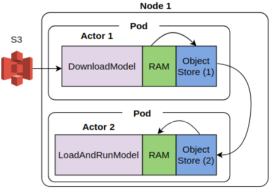
In this post, I’ll describe the results of some experiments I’ve been conducting recently regarding data transfer speed between Ray actors via object replication across plasma stores of Ray workers vs. downloading data from S3 into the process memory of Ray actors. All the code for this project is here.
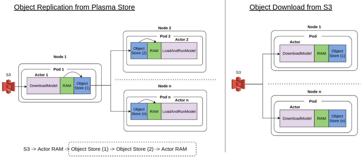
For context, in a distributed system, scattering data to nodes comprising a distributed cluster is a common task. For example, a call center call analysis system that transcribes voice call recordings into text using a speech2text model and runs a series of text analysis processes (such as named entity recognition, text classification or sentiment analysis) needs to first load the speech2text model to all nodes that need it. This can be done in two ways. First, some task in the distributed system loads the model data from a data store such as S3 into “local” memory and then scatter it to other nodes. Second, each node downloads the model from the data store independently. Intuition suggests the first method may be faster because data transfer is happening locally across the nodes in the cluster. This post will analyze if this intuition is really true and related nuances. The picture below shows the data transfers involved in the two scenarios.
The specific distributed computing system used in this investigation is Ray. Ray enables arbitrary functions to be executed asynchronously on separate Python workers. In this post, I’ll assume a high level of Ray and kubernetes knowledge, specially running Ray on kubernetes. Before I get to the main topic of the post, I want to go over three areas that aren’t covered well in the documentation in my opinion.
Structure of a Ray cluster
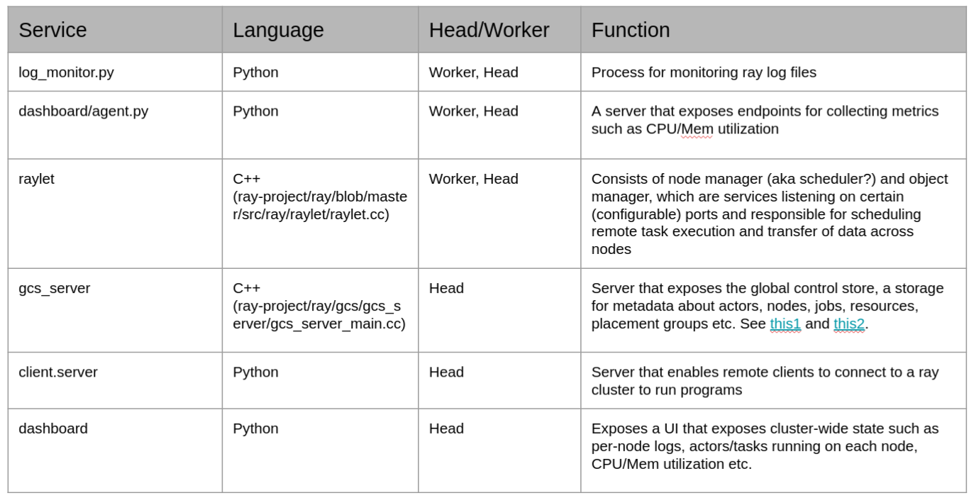
Ray consists of a set of services that run on the nodes of a Ray cluster to schedule and manage execution of tasks, track the global state of the system such as the number of actors and their resource constraints, and expose logs emitted by task execution to a dashboard UI. Every Ray Cluster has a head node and several worker nodes. A node (a highly overloaded term) in this context is simply a collection of services. When Ray is deployed on a kubernetes cluster, Ray head and workers are running as kubernetes pods. These pods are also sometimes referred to as “head node” and worker node”. This usage of node shouldn’t be confused with a kubernetes node, which refers to an EC2 instance in a kubernetes cluster. In this post, I’ll use the term compute instance or EC2 instance for a kubernetes node to avoid confusion.
The head node runs all the services that worker nodes run, and a few others. Services are long running tasks that are implemented in Python and C++ and have a many-to-one relationship to Linux processes. For example, the node and object manager services run on the Raylet process. The table below shows the name and function of services comprising a Ray cluster and other related information.
A good way to see a list of processes running on the head and worker nodes is to exec into the head and worker pods on a Ray kubernetes cluster and see a list of running processes. Because these pods are only running Ray and no other applications, this is a much smaller list of processes than is normally running on a Linux system. You can also use lsof to see which ports these processes are listening on. The screenshots below show this in action.


Remote task execution
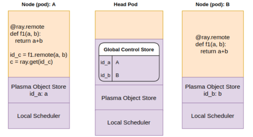
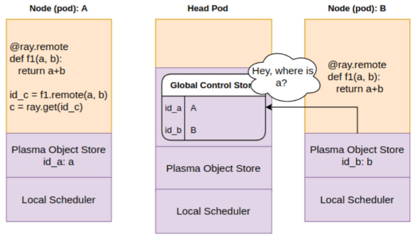
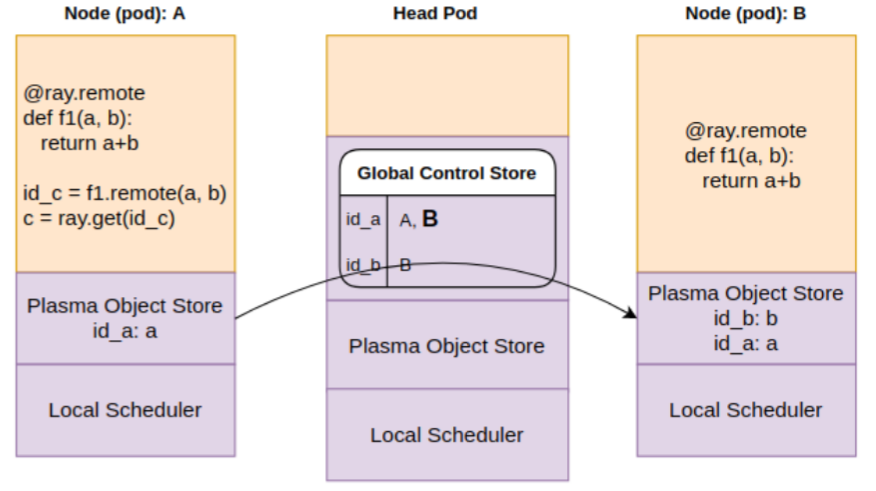
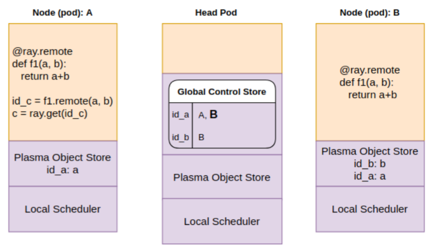
The second topic is the mechanics of a remote task execution, which is not covered in the documentation at all, but provides great insight on how the various sub-systems of Ray work together to enable remote task execution. The diagrams below show this sequence in detail.
Let’s say we have two worker nodes and a head node in our Ray kubernetes cluster. Each of these nodes are running as a kubernetes pod. These head and worker nodes could be running on the same compute instance or separate instances. A remote function f1 is invoked and its return value is fetched using ray.get. As you know, a remote function invocation is non-blocking, meaning that it returns immediately with a reference to the function return value(s). To retrieve the actual return value(s), one must call ray.get on the reference. This call will block until the results of the function execution are available.
In the picture below, note that each pod has its own instances of the Ray scheduler (implemented in the raylet process) and plasma object store. The head pod maintains (in Redis I believe) and exposes a Global Control Store (GCS) that records (among other things) on which pods data items generated by the application live. In our scenario, data item “a” is located on node A, and “b” is located on node B.
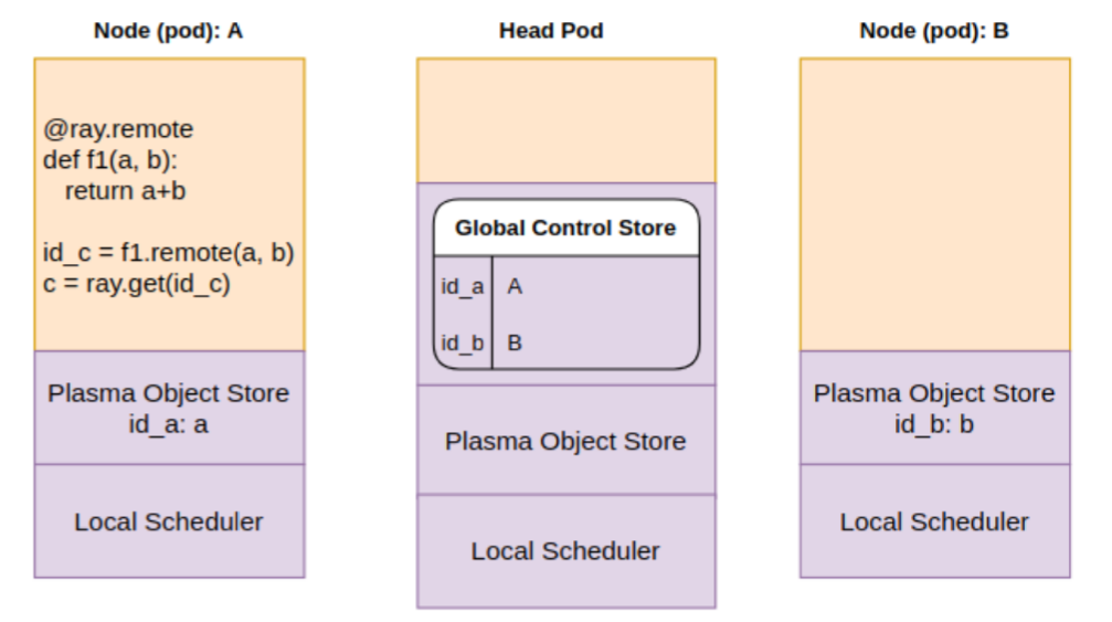
Step 1: Scheduler looks at the the GCS for where objects “a” and “b” are present and decides to schedule the function f1 on node B.
Step 2: Scheduler realizes only “b” is on the local object store. It queries the GCS to get the location of “a”
Step 3: Scheduler learns that “a” is on pod A. It is copied over to the object store on pod B via object store replication
Step 4: Scheduler finally schedules f1 for execution, copies over “a”, “b” from object store to process memory and runs f1
Now lets look at the sequence of operations involved with fetching the result “c”.
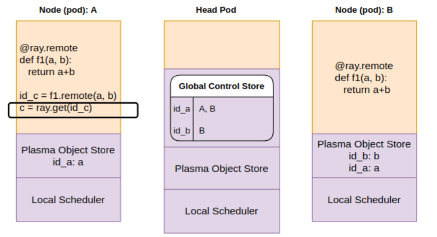
Step 1: Local scheduler on pod A is executing the get on future id_c. It checks the object store locally — which doesn’t have an entry for id_c yet.
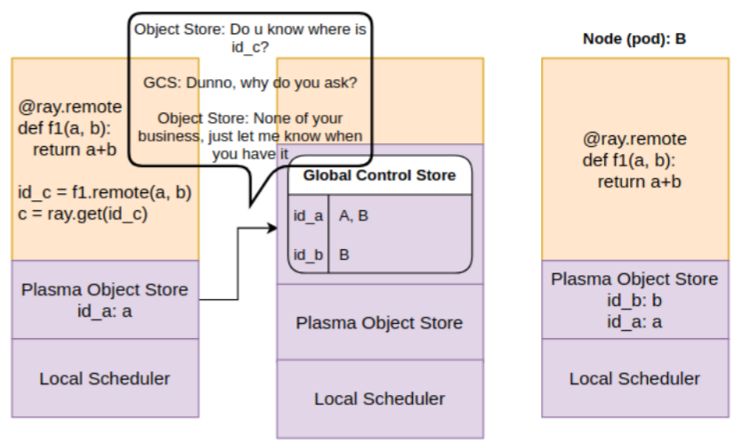
Step 2: The local object store asks GCS for id_c. Since GCS doesn’t have it, a callback is registered with GCS.
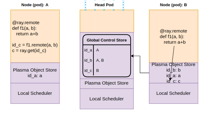
Step 3: In the meanwhile, add completes on node B. The data is stored in the objects store on B.
B object store informs GCS about availability of results of id_c. This is registered in the object table.
Step 4: GCS invokes the callback on A, notifying the availability of id_c on B.
The object store on A replicates id_c from B. The get operation is finally unblocked
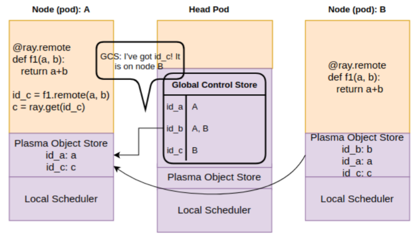
Hope these pictures make it clear how remote function execution and fetching results happen. Notice that Ray doesn’t provide a global object store. The object store is specific to a worker pod. There can be several worker pods on a kubernetes EC2 instance and several instances in a kubernetes cluster. These object stores have a R/W bandwidth, meaning that transferring data across local object stores involves latency. Measuring this latency is one of the objectives of this post.
Ray Cluster on Kubernetes
The third topic is Ray’s support for setting up a cluster on kubernetes. Again, I’ll assume general familiarity with kubernetes. A powerful feature of kubernetes is the ability to extend the control plane by creating a Custom Resource Definition (CRD), A which is an extension of the Kubernetes API that is not available in a default Kubernetes installation. Together with Custom Controllers which update the current state of Kubernetes objects in sync with your declared desired state, CRDs form the operator pattern that allows for extending the kubernetes control plane by encoding domain knowledge for specific applications.
Ray uses this pattern by providing a custom resource called RayCluster. A RayCluster consists of descriptions of a head node and multiple worker nodes. The description includes standard pod description fields such as the docker image, CPU/Memory requests/limits and Ray specific fields such as resources, autoscaling parameters etc. See documentation about Ray’s kubernetes integration for details.
Some of the cool features of Ray’s kubernetes integration are that it allows for a single operator to maintain the state of multiple RayClusters, each in their own namespace, as shown in the diagram below.
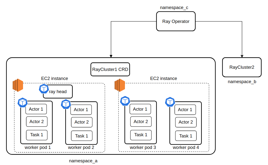
In this example, there are two RayClusters, running in namespace_a and namespace_b, each managed by a Ray Operator running in namespace_c. RayCluster1 has a head pod and 4 worker pods. Two worker pods and the head pod are running on on one EC2 instance and the other two worker pods are running on another EC2 instance. Each worker pod has several Ray actors and tasks running. Ray will handle scheduling workers to nodes, unless the user provides specific scheduling directions using kubernetes node placement features such as nodeName, affinity or nodeSelector. If no node in your cluster is able to satisfy the pod’s memory/resource requirements, that pod will remain in pending state.
You can change the desired state of a RayCluster (eg., by modifying the CPU/Memory limits/requests of a Ray worker, or the autoscaling settings) and apply the changes. Ray operator will automatically terminate the pods affected by the changes and start new ones. Ray will also automatically launch new worker pods if need be, respecting the autoscaling settings (minWorkers and maxWorkers)
My Ray-kubernetes cluster setup
I used kops (version 1.23.0) to set up a kubernetes cluster on AWS. I created a kops instance group for Ray consisting of t2.xlarge spot instances using the following command:
|
1 |
kops toolbox instance-selector raynodes-ig --vcpus-min=4 --vcpus-max=4 --memory-min 8gb --memory-max 20gb --node-count-max 1 --node-count-min 1 --usage-class spot --subnets us-east-1a --allow-list t2.x* --node-volume-size 64 |
Now you can edit the instance group using kops edit raynodes-ig and change the min/max node count to the desired number of instances in your cluster and run kops update cluster. Using spot instances can result in considerable savings on compute cost. The attached instanceGroup yaml is shown below for reference.
|
1 2 3 4 5 6 7 8 9 10 11 12 13 14 15 16 17 18 19 20 21 22 23 24 25 26 27 28 29 30 31 32 33 |
# Please edit the object below. Lines beginning with a '#' will be ignored, # and an empty file will abort the edit. If an error occurs while saving this file will be # reopened with the relevant failures. # apiVersion: kops.k8s.io/v1alpha2 kind: InstanceGroup metadata: creationTimestamp: "2022-03-26T17:51:46Z" generation: 44 labels: kops.k8s.io/cluster: dev.k8s.local name: raynodes-ig spec: cloudLabels: k8s.io/cluster-autoscaler/dev.k8s.local: "1" k8s.io/cluster-autoscaler/enabled: "1" image: 099720109477/ubuntu/images/hvm-ssd/ubuntu-focal-20.04-amd64-server-20220308 machineType: t2.xlarge maxSize: 0 minSize: 0 mixedInstancesPolicy: instances: - t2.xlarge onDemandAboveBase: 0 onDemandBase: 0 spotAllocationStrategy: capacity-optimized nodeLabels: kops.k8s.io/instancegroup: raynodes-ig role: Node rootVolumeEncryption: false rootVolumeSize: 64 subnets: - us-east-1a |
Obtaining STS Credentials for S3
I use the s2t-medium-librispeech-asr speech2text model in this investigation. I downloaded the model from huggingface and uploaded the model files to a S3 bucket. I then created an IAM Role (role 1) with read access to the bucket and added the IAM role (role 2) attached to the worker EC2 instances of my kubernetes cluster (nodes.dev.k8s.local by default on kops) to the trust relationship of role 1. With this set up, code running on a worker node of the kubernetes cluster is able to assume role 1 and create a boto3 client using the assume role credentials to download files from the S3 bucket. If you are unfamiliar with these concepts, I recommend reading up about how IAM works on AWS. Incidentally, the fact that any pod on a kubernetes cluster has the same level of IAM permissions as the IAM role attached to the EC2 instance is a security hole. There are solutions such as Kiam and IAM roles for service accounts designed to address this vulnerability.
I also implemented a “Token Vending Machine” by using Hashicorp vault to assume role1 for me and provide the STS credentials. This solution is more secure, because Vault can use the kubernetes token review service to verify the pod’s identity before providing the credentials requested. I only mention this in passing because you’ll see the code for it in utils.py but these topics are unrelated to the main subject of this post
Data transfer analysis: scenarios
With these preliminaries out of the way, let’s take a more detailed look at the two scenarios we discussed earlier
Scenario 1: Object store replication
In the first scenario, we use a DownloadModel (called “Download” henceforth) task (see src/download_model.py) to download the Speech2Text model from S3 and the LoadandRunModel (called “Load” henceforth) actor (see src/speech2text.py) uses this model to run speech to text conversion on a test audio file. The Speech2Text model data must be transferred from the object store of the Download task to the pods running the Load actor. We wish to analyze the latency of this data transfer for the cases outlined in the table below.
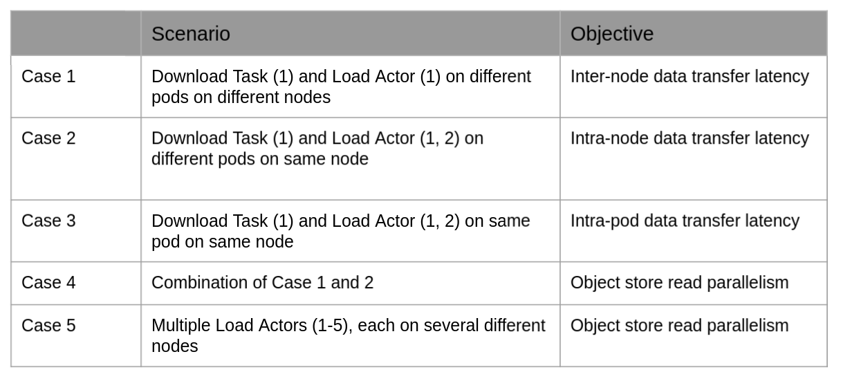
Scenario 2: Download from S3
In the second scenario, each Load actor downloads the model directly from S3, and no object store replication is involved. The table below lists the cases considered for this scenario:

Enforcing scheduling constraints
Implementing the scenarios listed above requires forcing Ray to schedule actors on specific pods and kubernetes to launch pods on specific nodes. This section describes the techniques used to accomplish this.
To force Ray to schedule actors on specific pods, I use actor resources. As shown in the picture below, Ray lets you annotate pod specs with a “rayResources” field. You can then annotate an actor definition with the custom resource or specify the resource during actor creation (as shown below) to launch specific actors on pods. The number in the rayResources field signifies the number of resources of that type used by that actor and hence can be used to constrain the number of actors using those resources. For example, if worker_pod_e: 3 in the picture below, then no more than 3 actors using worker_pod_e: 1 can be scheduled on that pod, subject to other resource constraints (CPU/Memory).
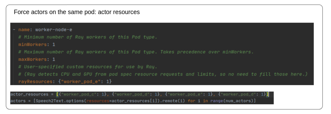
A related technique is to specify CPU and memory requirements in the actor or task definition. This can be used to ensure that the actor or task is scheduled on a pod with the necessary resources (as specified in the pod spec), lowering the possibility of out-of-memory errors.
To force kubernetes to place pods on specific nodes, several node placement techniques such as nodeName, affinity and nodeSelector are available. I use nodeName in this work.
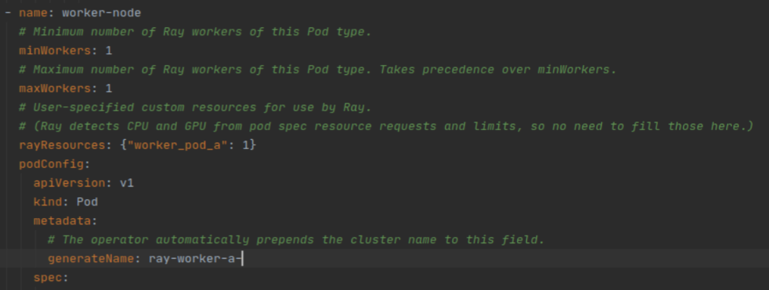
Another useful technique is to use the “generateName” field in the pod metadata to give descriptive names to the kubernetes pods, making it easier to see which pods are launched on which nodes.

Results
In this section I’ll show the results for each of the cases outlined above along with some observations. Let’s start with scenario 1 – object store replication.
Object store replication – Case 1: Base case
In this case, there is a single Download task and Load actor and they are scheduled on different nodes. We are interested in measuring the time taken to replicate the speech2text model data from the object store of the download task, across node (EC2 instances where the task and actors are running) boundaries and finally into the process memory of the Load actor. The picture below shows the hops involved.

Here’s a screenshot of the Ray dashboard after the data transfer has finished. The Download task was scheduled on the ray-head on PID 802. It shows IDLE because the task execution has finished. The Load actor was scheduled on worker-b pod, which is running on a different EC2 instance than ray-head.

| # LoadAndRunModel Actors | Data Transfer Time (sec) |
| 1 | 5.4 |
This implies a data transfer rate = 564/5.4 ~ 104 Mbps
Object store replication – Case 2: Download and Load actors on the same node
In this case, the data transfer stays internal to the node Download task and Load actors are running on, and hence we expect a higher data transfer BW. This is indeed borne out.

The table below shows the data transfer BW for one and two Load actors. The BW is nearly twice that of case 2, and doesn’t change much when the additional Load actor is added. This suggests that plasma store is able to support concurrent reads, but further experiments are required to fully validate this hypothesis.
| # Load actors | Data Transfer Time (sec) |
| 1 | 2.59 |
| 2 | 2.61 |
It is good to learn how to validate that the Download task and Load actor are indeed running on pods in the same EC2 instance. The screenshot of the Ray dashboard shows that the Download task was launched on pod worker-d, while the Load actors were launched on worker-f and worker-e.

Now we can use kubectl get pods -o=wide to see which nodes these pods are running on. The output shows they are all running on the same EC2 instance.

To recap how to force actors and tasks to run on the same EC2 instance, we use custom resources to force actors to be scheduled on specific worker pods and use nodeName field in the podConfig to force kubernetes to schedule those worker pods on a certain EC2 instance. You must ensure the instance has sufficient CPU/Memory resources to accommodate the pods, otherwise the pods will be in a pending state.
Object store replication – Case 3: Download and Load actors on the same pod
In this case, we’ll use custom resources to force the Download and Load actors on the same Ray worker pod. Since the plasma object store is per pod, this eliminates the need for data transfer across object stores. Data only needs to be transferred from the object store to the process memory of each actor.
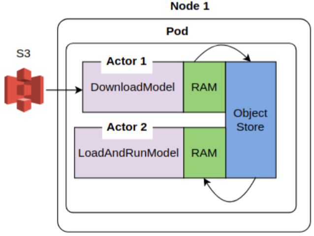
Similar to case 2, the table below shows the data transfer BW for one and two Load actors. The BW is about 20% higher than case 2. I had expected the data BW to be much higher. Perhaps object store to process memory copy is a more expensive than I thought, or some other limiting factor is involved.
|
# Load Actors |
Data Transfer Time (sec) |
|
1 |
2.23 |
| 2 |
2.4 |
The screenshot of the Ray dashboard below shows that the Download task and Load actors are scheduled on the same worker pod and share a plasma store

Object store replication – Case 4: Mix of case 1 and 2
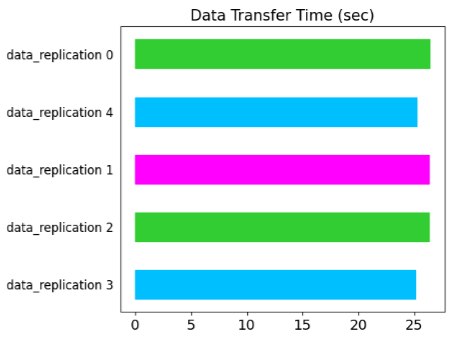
This case will consider a mix of the case 1 and case 2 – two Load actors (shown as data_replication 2, 3 in the bar chart below) on the same node running the Download task and two Load actors (data_replication 0, 1) on a different node.
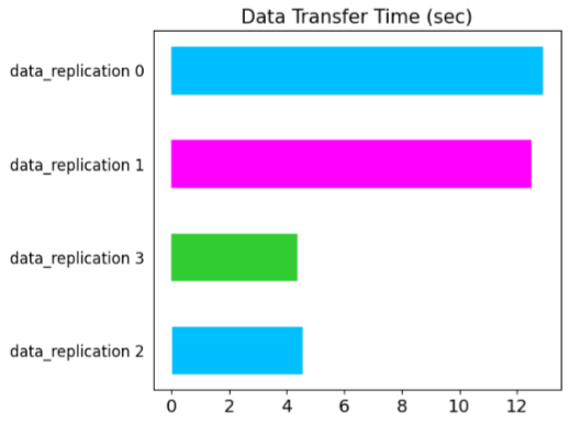
The data replication times for actors 0, 1 are ~ 3X higher, confirming the findings presented in case 1 and 2.
Object store replication – Case 5: Each Load actor on a different node
In this case, we’ll vary the number of Load actors from 1 – 5, scheduling each on a different EC2 instance and examine the data transfer time. The table below shows the data transfer times. Plotting the times against number of actors reveal a nearly straight line.
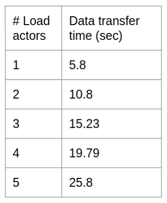
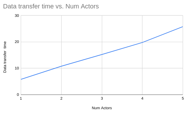
Average data transfer BW = size of data transferred / slope of the graph ~ 100 Mbps
In case 2 and 3, we saw that the data transfer BW is higher when Download and Load actors are scheduled on the same node. This suggests that the plasma store is able to support a higher data transfer BW and we appear to be I/O bound by the EC2 instance’s network BW. Data transfer also seems to be interleaved, since the data transfer operation for each Load actor finish around the same time as indicated by the bar chart below.
This concludes the analysis of scenario 1. Next, lets consider scenario 2 where each Load actor downloads the speech2text model directly from S3 and no object store replication is involved. I’ll just show results for case 2 and 4 for brevity.
Download from S3 – Case 2: Each load actor runs on a different EC2 instance
Here, the speech2text model is downloaded directly to the process memory of each Load actor, without any object store replication involved (see diagram below). We’ll vary the number of Load actors from 1 – 5 and examine the load times.
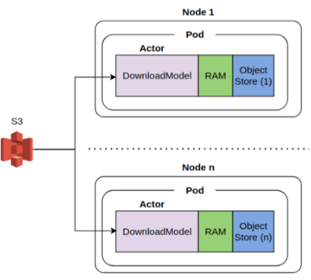
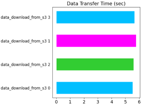
The table below shows the results. The download times are nearly independent of the number of actors and the data transfer BW is very similar to what we saw earlier for object store replication across nodes. This indicates that S3 supports a high degree of read concurrency and the data transfer BW is indeed upper bounded by the network I/O BW of the EC2 instance.
| # Num Actors | Download time (sec) |
| 1 | 5.4 |
| 2 | 5.4 |
| 3 | 5.4 |
| 4 | 5.6 |
Download from S3 – Case 4: Some load actor run on the same EC2 instance
This case will examine what happens two Download actors (3 and 4 in the figure below) run on the same instance. The download times for those actors are nearly twice that of other actors that run on separate instances. This further validates that the download time is limited by the network I/O BW of the EC2 instance.
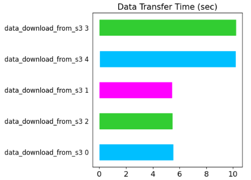
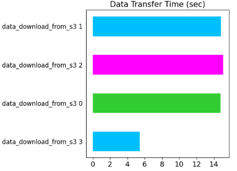
Similar behaviour is observed when multiple Download actors are scheduled on the same worker pod. As shown in the figure below, actors 0, 1, 2 are scheduled on the same pod. The data transfer time for those actors is nearly 3x that of actor 3, which is scheduled on a separate EC2 instance. The Ray dashboard screenshot also shows that data is downloaded directly into the process memory of each actor without plasma store’s involvement.

Conclusions
- Ray doesn’t provide any out-of-the-box cluster-wide or even compute instance-wide distributed data store. Ray’s plasma store is per Ray worker. This means that data must be replicated when actors are running on different Ray workers.
- When the workers are running on the same compute instance, the data replication is faster – around 200 Mbps.
- Plasma store appears to offer some degree of read concurrency (object store replication, case 2), although this needs to be investigated further.
- When the workers are running on different compute instances, data replication goes through network I/O and is limited to ~100 Mbps. This should be seen as a network BW limitation rather than a limitation of Ray.
- S3 offers great read concurrency. Multiple actors running on separate compute instances can read an object from a S3 bucket in parallel
- S3 reads by actors running on the same node is network I/O limited
- All of this means that if you need to transfer a lot of data between actors, you should schedule those actors on workers running on the same compute instance. If the workers must run on separate compute instances (eg., due to resource constraints), you may be better off writing the data to S3 and having the workers read data from S3, rather than relying on object store replication.

Super to see this all put together after seeing some of the pieces previously. I also appreciate the bits of humor integrated into it! 🙂