
The purpose of the this post is to provide my thoughts on what goes on during an iteration of POSIT. This post is not meant to be a detailed description of POSIT. Please refer to 1and 2for a detailed and thorough description of POSIT.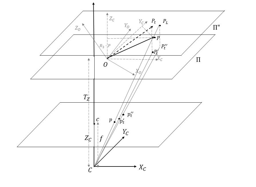
The figure above demonstrates the geometry of the problem. The camera coordinate system is defined by  . The camera center is denoted by
  and the image plane is located at a distance of
  from the camera center. The center of the image is denoted by
  and thus the vector
  represents the optical axis of the camera. The object point P is known in the object coordinate system denoted by
  . There is an unknown rotation and translation of the object coordinate system with respect to the camera coordinate system. The rotation matrix and translation vector representing this transformation are denoted by
  and
and  respectively.
The vector  is known only in the object coordinate system, not in the camera coordinate system. This means we don’t know the coordinates of the vector shown in the figure. Indeed, from the definition of the rotation matrix, the coordinates of in the camera coordinate system are
  .
.
The point projects to a point  on the image. The coordinates of are known. Thus, the known quantities in POSIT are:
- The coordinates of in the object coordinate system
- Camera intrinsic parameters and
- Coordinates of the image point corresponding to each object point
From these known quantities, we wish to determine the transformation ( ) between the camera and the object coordinate system.
First let’s consider the general equation for perspective projection. Following [1],

The image coordinates  and
and  are given by:

Note that appears both in the numerator and denominator. In the denominator, it adds a contribution equal to the projection of on the optical axis of the camera. Thus, each image coordinate is scaled in proportion to the distance of the corresponding 3D point from the camera. This is a standard feature of perspective projection. However, because appears both in the numerator and denominator, we can’t write the equation above in a linear form and apply linear algebra techniques to solve for  and
and  .
.
Dividing the numerator and denominator by  and denoting
  by
by  , we obtain:

Again following the notation in [1], let’s denote  by
by  . For object points that are far from the camera and/or lie close to the image plane,
  . The
. The  depend on the object point coordinates and the object-camera transformation and are different for each point. Now if somehow we know the values of for each object point, then we can write the perspective projection equation in a linear format:

Multiplying by on both sides and writing in matrix form,

Now we can solve for and using linear algebra techniques. It is important to understand that because we fixed the , solving the linear equation above is not equivalent to solving the general perspective projection equation. Instead, solution to the equation above corresponds to finding the and such that the image coordinates of the scaled orthographic projection of the point on the plane given by  are
are  .
.
Let’s now look at iteration  of POSIT. From the previous iteration, we have an estimate of the rotation and translation between the object and the camera coordinate system. Let’s denote this rotation and translation by
  and
and  . The object point transformed by this transformation is shown as
  in the figure above. Its coordinates in the camera coordinate system are
  . From this rotation and translation, we compute new values for the
  using the formula
  . Here
  is the object point index. Now consider equation 5 in [1]. This equation defines the objection function that is minimized in each iteration of POSIT. The objective function is a sum of
  defined as:

The  term in the equation above represents the scaled orthographic projection of the point of intersection of the line of sight of image point with a plane parallel to the image plane passing through the point
  (denoted by
  ). To see this, consider the line of sight through image point . A point on this line of sight can be represented as
  . Since is the image of under perspective projection, lies on this line of sight, but we don’t know the corresponding .
The point of intersection of this line of sight with the plane  can be obtained by setting
  . Thus the coordinates of this point of intersection (shown as
  ) are
) are  . From the definition of the perspective projection, the image coordinates (denoted by
  ) of the scaled orthographic projection of this point on the plane at
  are therefore
  =
=  .
.
As stated before, the first term in the definition of corresponds to the scaled orthographic projection of , denoted by  . Thus at each iteration of POSIT, we compute rotation and translation such that the distance between the scaled orthographic projections and are minimized in a least square sense. This makes sense as when we have the correct rotation and translation, points
  (and thus points
  ) coincide. Thus the vector
  is a measure of how far we are from the correct pose.
Leave a Reply