
In part 1 of this series, we examined the issue of depth of field and its relationship with aperture and focal length in detail. We reached the conclusion that for lenses with a short focal length focused on objects > 10m from the camera, the depth of field is nearly infinite and all visible objects are in good focus. Let’s now examine the issues of shutter speed and ISO.
Shutter Speed (denoted as Tv on most cameras) is the time for which the camera shutter is open. A higher shutter speed exposes the camera sensor for a shorter length of time and vice versa. Shutter speed also directly affects the amount of light entering the camera. While taking pictures from a moving platform, we want to have a high shutter speed, so the camera perceives the scene as stationary for the short duration that the shutter is open. Contrast this with recording star trails, where you want as low of a shutter speed as possible, so you can track the movement of the stars across the sky.
How high does the shutter speed need to be? We can use a calculation similar to what we saw for the circle of confusion in part 1. Consider an aerial platform equipped with a Canon S100 (focal length (f) = 5.4mm, frame size: 4000 by 3000, sensor height = 7.44mm) moving at a speed  at a height of
  above the ground. We want the shutter speed to be such that the line of sight to a given scene point moves by less than a pixel while the shutter is open. This makes sense as we don’t want a scene point as seen from the camera to bleed over into the adjacent pixel on the image.
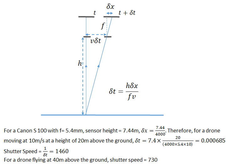
As shown in the calculation above, we obtain quite achievable values for the shutter speed. Even relatively cheap point and shoot cameras allow for shutter speeds of around 2000. Furthermore, modern cameras are equipped with a variety of optical and digital image stabilization mechanisms, which help to mitigate the effect of camera movement and camera shake.
Let’s now consider ISO. ISO is a measure of the level of sensitivity of the camera to available light. The lower the ISO number, the less sensitive the camera is to light and vice versa. With increased sensitivity, the camera sensor can capture images in low-light environments without having to use a flash. But higher sensitivity comes at a price– it adds grain or “noise” to the pictures. Let’s look at two pictures of the same scene with different ISO values.
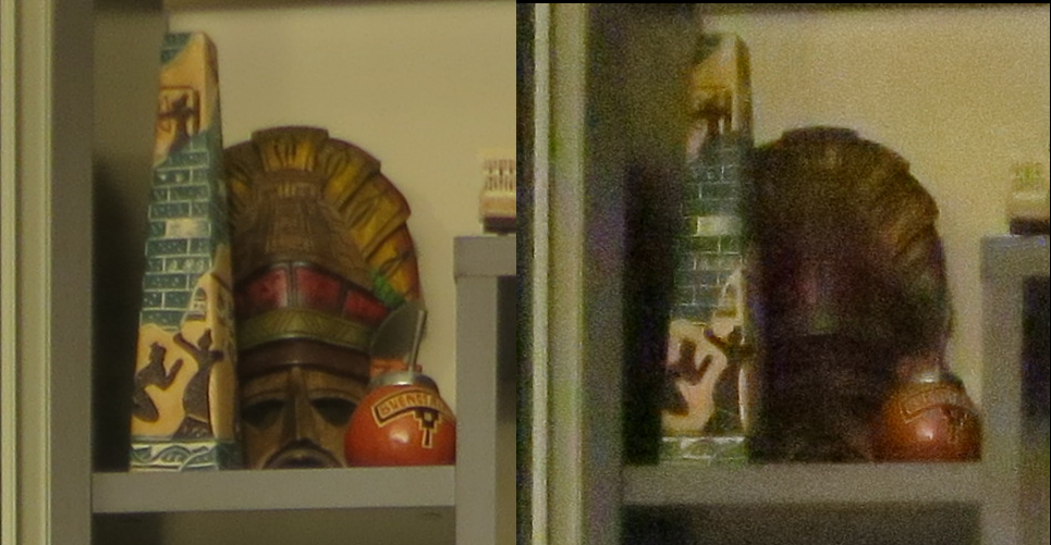
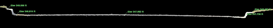
As you can see the picture with the lower ISO has a lot less noise. This can make a big difference in the quality of the point cloud that results from these pictures. For example, let’s take a look at slices from two photogrammetry generated point clouds:

Therefore, while taking aerial photographs suitable for photogrammetry, we want to keep the ISO as low as possible. There is a trade-off however. Setting the ISO to a low value makes the camera less sensitive to light, which means the shutter speed needs to be low so that the sensor is exposed to enough light to produce pictures with acceptable brightness. For example, for the pictures shown above, the camera chose a shutter speed = 1/40 sec for the higher ISO picture and a shutter speed of 0.4 sec for the lower ISO picture. Clearly, a mechanism is needed that strikes the right balance between the shutter speed, ISO and the aperture. The aperture can usually be set to the highest allowable value, so it’s mostly just the shutter speed and the ISO that need to be dynamically adjusted as the drone carrying the camera is flying over the scene.
CHDK
CHDK (Canon Hacker Development Kit) provides an API to control the camera parameters dynamically. CHDK is a firmware enhancement that operates on a number of Canon Cameras. CHDK gets loaded into your camera’s memory upon bootup (either manually or automatically). It provides additional functionality beyond what is natively provided by the camera firmware. CHDK is not a permanent firmware upgrade, the user can easily remove it and revert back to the original camera firmware.
CHDK exposes a number of functions that can be accessed from Lua and Basic and be used to set various camera parameters such as aperture, shutter speed etc., to implement custom features. We won’t discuss using CHDK in detail in this post, there are many excellent references on the web. The wiki page about CHDK is a good place to start:
http://chdk.wikia.com/wiki/CHDK_in_Brief
In the remainder of this post, we’ll discuss one particular CHDK script called KAP (short for Kite Aerial Photography, as the script was first developed for aerial photography from cameras mounted on kites and later adopted for UAVs). KAP is an intervalometer (allows the user to set the shooting interval) script that automatically controls shutter speed, aperture, ND filter, and ISO settings so as to maintain the fast shutter speeds needed in aerial photography.
The script’s operation is not hard to understand. The script first meters the scene using:
|
1 |
bv96raw=get_bv96() |
The script then determines the ISO given the scene brightness, the target Tv and the target Av. If the resulting ISO falls in the range of Min to Max1, it takes the picture at the appropriate ISO.
|
1 2 3 4 5 6 7 8 9 10 11 12 13 14 15 16 17 18 19 20 21 22 23 24 25 26 27 28 29 30 31 |
function basic_iris_calc() tv96setpoint = tv96target av96setpoint = av96target -- calculate required ISO setting sv96setpoint = tv96setpoint + av96setpoint - bv96meter -- low ambient light ? if (sv96setpoint > sv96max1 ) then -- check if required ISO setting is too high sv96setpoint = sv96max1 -- clamp at first ISO limit av96setpoint = bv96meter + sv96setpoint - tv96setpoint -- calculate new aperture setting if ( av96setpoint < av96min ) then -- check if new setting is goes below lowest f-stop av96setpoint = av96min -- clamp at lowest f-stop sv96setpoint = tv96setpoint + av96setpoint - bv96meter -- recalculate ISO setting if (sv96setpoint > sv96max2 ) then -- check if the result is above max2 ISO sv96setpoint = sv96max2 -- clamp at highest ISO setting if so tv96setpoint = math.max(bv96meter+sv96setpoint-av96setpoint,tv96min) -- recalculate required shutter speed down to tv minimum end end -- high ambient light ? elseif (sv96setpoint < sv96min ) then -- check if required ISO setting is too low sv96setpoint = sv96min -- clamp at minimum ISO setting if so tv96setpoint = bv96meter + sv96setpoint - av96setpoint -- recalculate required shutter speed if (tv96setpoint > tv96max ) then -- check if shutter speed now too fast tv96setpoint = tv96max -- clamp at maximum shutter speed if so av96setpoint = bv96meter + sv96setpoint - tv96setpoint -- calculate new aperture setting if ( av96setpoint > av96max ) then -- check if new setting is goes above highest f-stop av96setpoint = av96max -- clamp at highest f-stop tv96setpoint = bv96meter + sv96setpoint - av96setpoint -- recalculate shutter speed needed and hope for the best end end end end |
If scene brightness is too low with ISO at Max1, it lowers the f-stop setting as needed, down to the minimum f stop setting (maximum aperture)
- If still more exposure is needed, it raises the ISO, up to the Max2 setting
- If still more exposure is needed, it slows the shutter speed below target to get a good exposure.
If the scene brightness is too high with ISO at Min, it raises the shutter speed, up to your Max setting.
- If exposure is still too high, it raises the f-stop, up to the Max setting for the f-stop.
- If exposure is still too high, it raises shutter speed above the Max setting to get a good exposure.
Here Min, Max1, Max2 etc., are user adjustable script parameters.
Linearizing Aperture, Shutter Speed and ISO
You might have noticed that in the equations above, we are simply adding the values of ISO, aperture and shutter speed. These are very different properties, so how can we simply add or subtract one from the other? This is achieved using the APEX (The Additive System for Photographic Exposure) system. A good explanation of the APEX system is in the following wiki article:
https://en.wikipedia.org/wiki/APEX_system
APEX uses the exposure equation, which establishes a relationship between the aperture A (expressed as the f number), shutter speed (1/T), the scene brightness (B), and the ISO (S, also known as “film speed”).

Here, K is a constant, called the meter calibration constant. Taking the base 2 logarithm of both sides, we obtain:

This linearizes the relationship between shutter speed, aperture, scene brightness and ISO, which can be expressed as:

Here  denotes the exposure value. The various constants are mysteriously subsumed into the exact formulas for
  etc. For example, for the canon cameras, the exact formula for
  is
is

If you look at the top part of the KAP.lua file, you can see the mapping between aperture, shutter speed and ISO values to the respective Av, Tv and Sv values. For example, an ISO of 80 maps to a Sv = 381, following the formula shown above. I don’t know the exact expressions for the other parameters, but it’s not really important to know them, a basic understanding of how the parameters are related to each other is enough.
Another interesting article that provides a historical perspective on how proper values for various camera parameters were determined in the early days of photography is this one:
http://brayebrookobservatory.org/BrayObsWebSite/HOMEPAGE/PHOTO_EXP_CALC_HIST.html
Some KAP Tips and Tricks
The KAP.lua features a continuous mode (set by selecting “Burst” for the Shot Interval), where scene metering and automatic adjustment of Av, Tv etc is done at the beginning when the script starts and then the calculated values are used for the remainder of the script execution. If you are surveying an area where the lighting conditions are largely uniform and want to shoot pictures as quickly as possible, then choose this mode. I’m able to get pictures roughly once every second, which is great when I’m flying the UAV at a lower altitude and need the pictures to be taken more frequently in order to ensure sufficient overlap between two successive pictures.
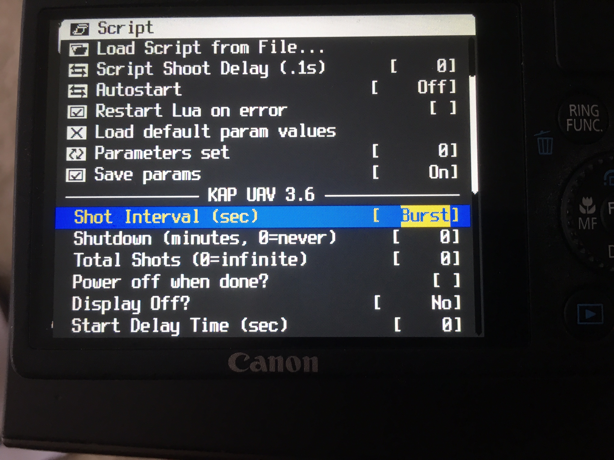
If you want the aperture, shutter speed etc to be adjusted dynamically for each shot, then choose the desired interval for the Shot Interval. In practice, the fastest you’ll be able to capture pictures in this mode is roughly every 4 seconds.
The KAP.lua script also saves the calculated values for Av, Tv etc., in a log file (KAP.log by default). The values are saved only when not shooting in continuous mode. In continuous mode, only the image file name and the time when a picture was taken is saved. Note that you can read the exact time (in milliseconds) when a picture was taken, which can be useful for geotagging a picture precisely. The exif tags typically only save the image file creation time to a resolution of a second, which is usually not sufficient. If your UAV is traveling at 10m/s, you have an uncertainty of 10m when trying to geolocate a picture from the exif tags, which is not good.
2015Dec10 12:17:18.370 65) IMG_4454.JPG
2015Dec10 12:17:21 meter : Tv:1/320 Av:4.0 Sv:80 808:808
2015Dec10 12:17:21 actual: Tv:1/1600 Av:4.0 Sv:400
2015Dec10 12:17:21 AvMin:2.0 NDF:NDout foc:infinity
It is typically good to set the desired aperture to the highest possible value on your camera (lowest f-stop), that way the ISO is set to the lowest that it can be.
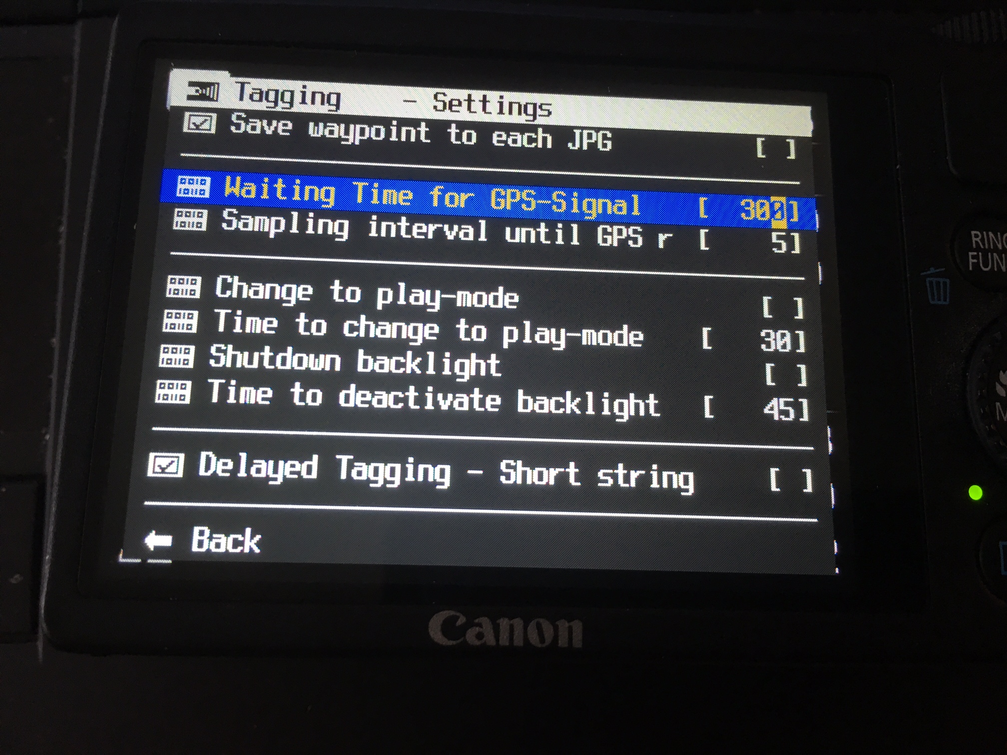
Another issue I noticed on my camera is that if I enable the “Save Waypoint to each JPG” setting under CHDK GPS settings, I start getting a “memory error” after a few pictures. This took me a while to figure out, so make sure that this is not enabled. Turning this setting off doesn’t prevent the GPS coordinates from being embedded in exit tags, I’m frankly not sure what this setting does.
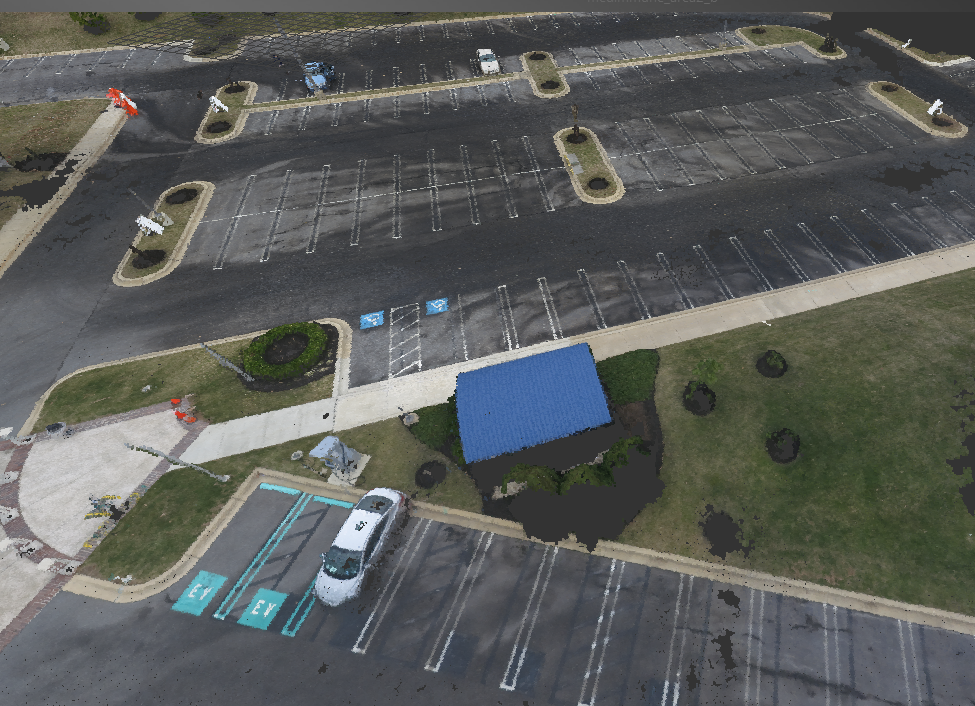
Here’s a point cloud constructed by applying photogrammetry to drone pictures captured using the techniques discussed here. Small terrain details such as curb boundaries, parking lot stripes etc., are clearly visible.
That’s it for now! Hope you’ll find this information interesting and useful.
Leave a Reply