
Over the last couple of months, I have been investigating techniques to improve the accuracy of my surveys and eliminate the need of using ground control points. The accuracy of the surveys are limited by the accuracy of the GPS device used to geolocate the pictures gathered during the survey. The accuracy of GPS devices used in commercial drones is typically of the order of a meter, which is hardly survey quality. So it became clear that I need to explore other techniques to get better positional accuracy.
Differential GPS techniques are commonly used to obtain better positional accuracy. Before examining these techniques in detail, let’s first look at how GPS itself works.
GPS (Global Positioning System) is a network of about 30 satellites orbiting the Earth at an altitude of 20,000 km. The system was originally developed by the US government for military navigation but now anyone with a GPS device, be it a SatNav, mobile phone or handheld GPS unit, can receive the radio signals that the satellites broadcast. There are multiple GPS systems set up by different countries – Galileo in Europe and Glonass in Russia. China, Japan and India have their own GPS satellite systems as well.
The GPS satellites orbit the earth in such as way that wherever you are on the planet, at least four GPS satellites are ‘visible’ at any time. Each one transmits information about its position and the current time at regular intervals. These signals, travelling at the speed of light, are intercepted by your GPS receiver, which calculates how far away each satellite is based on how long it took for the messages to arrive. This information can be used to pinpoint the location of the GPS receiver on earth. Incidentally, because the satellites are orbiting the earth at a high speed, the atomic clocks on board these satellites will run slightly slower than an identical clock on earth, due to relativistic effects. The GPS system takes into account these relativistic effects while triangulating to get the position of the receiver. So thanks to Albert Einstein for figuring out relativity, without which Google maps (and a host of other things) wouldn’t exist or be highly inaccurate.
The signal from the GPS satellites received on the ground has several sources of error which contribute to errors in the positional accuracy. Some of these sources of errors are ionospheric effects, satellite ephemerides and clock drift. Interestingly these errors are generally the same over large areas and drift only slowly with time. Differential GPS techniques use a pair of GPS receivers, one stationary (base station) and the other moving (rover) to estimate the signal error and apply a suitable correction to get a much more accurate position of the rover. It is possible to get a positional accuracy of ~2cm using high quality differential GPS techniques.
When I first learnt about RTK, I got so excited that I immediately rush ordered two u-blox Neo-6M (http://www.amazon.com/J-Deal-Aircraft-Controller-Antenna-Arduino/dp/B00ZOWY7PI/ref=sr_1_2?ie=UTF8&qid=1451102428&sr=8-2&keywords=neo-6m) GPS receivers from Amazon. As soon as the receivers arrived, I hooked them to my Arduino Mega and used the TinyGPS library to process the signals from the GPS unit. The GPS unit can be connected to the Arduino using UART (don’t forget that Tx on the GPS connects to Rx on the Arduino Serial Port) and you can use hardware Serial to receive the data from the GPS unit. The default baud rate is 9600 bps. The TinyGPS library can be used to extract various types of info (for example latitude/longitude) from the signals received by the GPS unit.
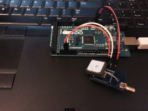
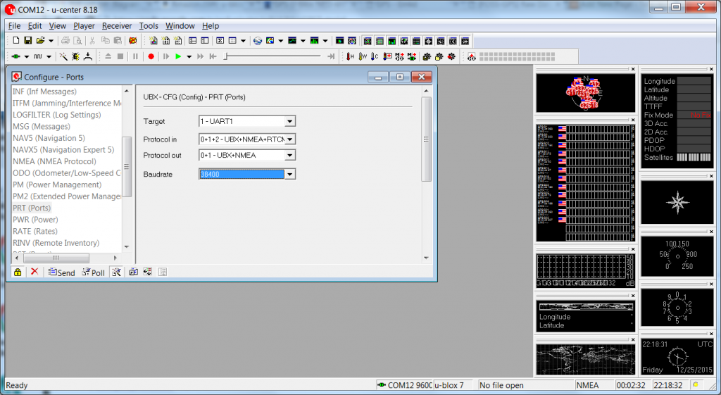
The other way to see the GPS data is to install u-center from u-blox (https://www.u-blox.com/en/product/u-center-windows) which allows you to visualize the GPS data and configure the GPS unit (control which messages you want to receive, set the baud rate and so on). You can connect the GPS unit to u-center running on your computer in two ways:
- Get a FTDI->USB cable (http://www.amazon.com/Gearmo-Header-cable-Chipset-Rasperry/dp/B004LC28G2/ref=sr_1_1?ie=UTF8&qid=1451103433&sr=8-1&keywords=ftdi+usb+cable) which allows you to directly connect the GPS Unit UART port to your computer’s USB port.
- Connect your GPS unit to an Arduino (would need an Arduino with at least two serial ports) and then simply pass the data received to the computer serial port
|
1 2 3 4 5 6 7 8 |
void loop() { while(gpsSerial.available() > 0) { // THIS IS THE MAIN LOOP JUST READS IN FROM THE GPS SERIAL AND ECHOS OUT TO THE ARDUINO SERIAL. Serial.write(gpsSerial.read()); } } |
Now in u-center, you’ll be able to see the data received from your GPS unit in a convenient graphical interface, as well as change various configuration options.
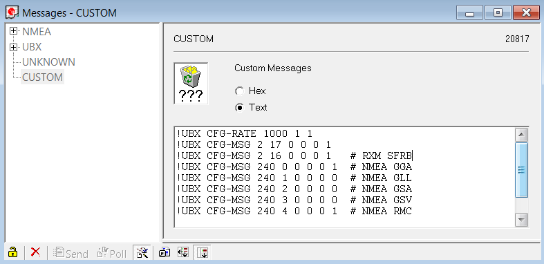
This is all well and good, but how about RTK? This is where I wish I had done a bit more research before rushing to buy the Neo-6M GPS unit. Turns out that in order to be used for RTK, a GPS unit must be able to provide the raw observation data (I believe the L1 signal carrier phase info) and satellite ephemerides. The Neo-6M doesn’t appear to be capable of doing so. There are some articles on the internet (http://lists.osgeo.org/pipermail/foss-gps/2014-April/001083.html) that seem to suggest that you can enable this data output by entering the following commands in the custom message window, however this didn’t work for me. If someone has been able to get this to work, please let me know!
So it appears that one has to buy a special class of GPS receivers that provide the raw information needed for RTK. In fact, if you look at the position/timing products on u-blox website (https://shop-america.u-blox.com/en/usd/3~101~AMERICAS/Position-Time/Standard-Precision-GNSS/NEO-series), they categorize these products in four categories:
- Standard Precision GNSS: The Neo-6M and Leah-6H and Neo-7M (used in 3DR copters) are in this category
- High Precision GNSS: These modules obtain better GPS accuracy using “precise point positioning” a technique that uses local SBAS satellites to estimate the ionospheric corrections. I don’t know much else about these modules.
- Dead Reckoning: These systems use a combination of inertial sensors and kalman filters to improve positioning performance in urban canyons, mines, tunnels etc. Since UAV’s generally operate with a clear view of the sky, dead reckoning corrections are not necessary
- Timing: These modules have a “T” at the end of the product name. They provide the raw timing information necessary for RTK calculations.
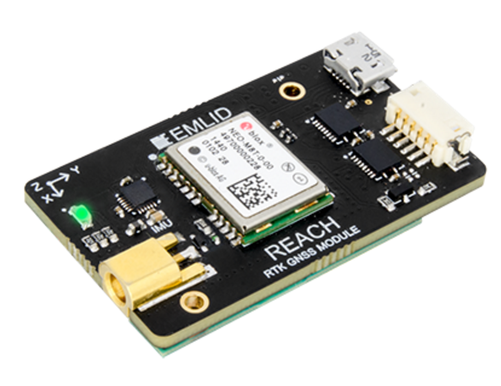
So I went ahead and ordered a Neo-8MT from CSG Shop. It will take a few days to ship unfortunately. Can’t wait to try them out! Incidentally, these are the same chips used in the “Reach” RTK system (http://www.emlid.com/shop/reach-rtk-kit/) which sells for ~500$ while the individual chips can be obtained for about $70 each. The Reach system also includes the antennas, USB cables etc, but it might lead to significant savings (in money and time, given that the January 2016 batch of the Reach units won’t ship until the middle of Jan at the time of this writing) to use the chips with RTKLib.
Note that since 3DR copters use the standard precision GPS units that don’t provide raw timing information, you’ll have to either replace the on-board GPS with the “T” version or install a separate GPS unit that logs the timing information for post processing later. Another issue is that AFAIK, the GPS info contained in the MavLINK logs is not detailed enough for RTK, so even if the GPS unit was able to provide such information, it is not logged by default and enabling such logging will require modifications to the Ardupilot code. It might be a simpler option to simply connect a second, timing enabled GPS unit connected to a data logging system. This data can then be post processed using RTKLib to obtain the precise flight path of the copter.
I’ll report back once I receive the units and get a chance to try all this out. However hopefully this information will clarify some of the questions around RTK and save you from buying the wrong GPS hardware.
Look for the Hex code to send using RTKLIB 2.4.2_p13 Navi.exe during startup. The hex bits to send are on open street maps ublox raw: https://wiki.openstreetmap.org/wiki/UbloxRAW
It worked for a cheap 6M ublox firm 7.03 that I had to enable raw using the RTKNAVI startup, however I still had to go into u-center after enabling the bits and send click on RXM-RAW message and send.
Restarted RTKLIB Navi.exe and the raw data was visible when connecting with Ublox protocol . On cheap GPS units or possible knock-offs, you may not be able to save this configuration (I’ve heard the memory is missing) If you need quality, buy a nice 6T or M8T from CSG shop. They are legitimate out of Europe.
!HEX b5 62 09 01 10 00 c8 16 00 00 00 00 00 00 97 69 21 00 00 00 02 10 2b 22
!HEX b5 62 09 01 10 00 0c 19 00 00 00 00 00 00 83 69 21 00 00 00 02 11 5f f0
That looks interesting. If anybody else is able to get this to work, please report back. It makes sense that there exists a way in SW to have the “regular” (non-T) u-blox chips send the raw data, because at a HW level they are likely identical to the “T” (timing enabled) chips