
Most applications of commercial drones today involve aerial photographs as an input. Taking good photos from a moving platform involves a number of challenges, some of which we’ll address in this series of posts. We’ll focus our attention on aerial photographs as an input to photogrammetry applications. Photogrammetry is a technique that uses image feature correspondences to extract the camera and scene geometry and then employs multiview stereo to construct a dense point cloud of the scene depicted in the photos. Photogrammetry is emerging as a disruptive technology in the areas of land surveying and construction site monitoring as it is able to reproduce scene geometry to an accuracy of around a cm which rivals that of laser scanners and is adequate for most surveying and building modeling tasks.
The accuracy of photogrammetry is determined by how well scene features can be resolved through image pixels. High mega pixel, sharp (low noise) pictures have a higher resolution and result in denser, more accurate and less noisy point clouds. However taking sharp pictures from a moving platform can be a challenge. In this series of posts, we’ll discuss how camera parameters such as shutter speed, aperture and ISO can be adjusted dynamically to take good quality pictures.
Image Formation Process
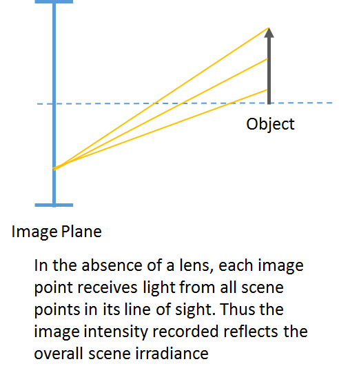
Let’s first understand how image formation occurs. Imagine what would happen if you were to take out the lens from an analog or digital camera (while leaving the shutter intact). What type of image will you get? It is likely that your image will be completely washed out, looking nothing like the scene in front of the camera. This is because each pixel on the sensor is being hit by light rays from all parts of the scene, and thus the pixel intensity will simply reflect the overall irradiance of the scene.
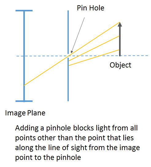
In order to form images that represent the scene, some mechanism is needed to focus the rays of light so that an image point only receives light from a single point in the scene. The easiest way to do this is to insert an opaque barrier with a small hole between the scene and the image plane. The hole will effectively act as a lens, allowing an image point to only receive light along the line of sight from the image point to the hole. This construction is called a “pinhole camera”
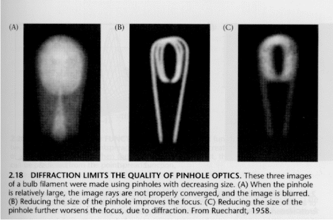
A pin hole camera has two major problems. The first is the trade-off between image sharpness and light collecting power. In order to create sharp images, the pinhole must be infinitesimally small (otherwise each image point will receive light from a pencil of light rays, instead of a single light ray). However a smaller pinhole results in lower overall light energy received by the pinhole image, thereby reducing the intensity of the image. The second is the issue of diffraction. Light bends as it passes by the edge of a narrow aperture. The amount of bending is given by:
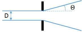

where  is the wavelength and
  is the aperture.
So, clearly, we need a mechanism that allows us to collect more light, without sacrificing the focus quality. This is where lenses come in.
Camera with Lenses
Lenses allow multiple light rays emanating from a single scene point to converge to a single point on the image, thereby increasing the intensity of light received by an image point. Light emanating from different scene points converge to distinct points on the image, thereby allowing each image point to represent the irradiance of a single scene point.
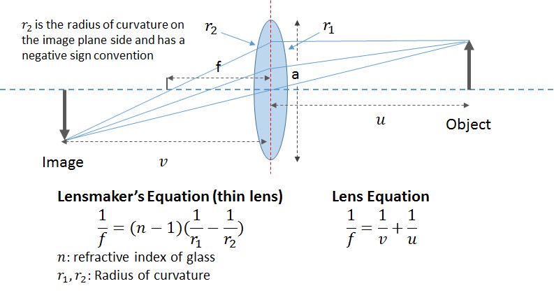
Lenses focus light rays emanating from a object point to a single point on an image located at a given distance from the lens center. The distance of the image plane from the lens center depends on the distance of the object from the lens center, as indicated by the lens equation shown below. For objects located at infinity (whose light rays are traveling parallel to the principle axis of the camera), all light rays are focused to a single point, called the focal point or focus. The distance of the focal point from the lens center is the focal length of the lens. Note that the notion of focus doesn’t arise for a pinhole camera, which only permits a single ray of light from a given object point to hit the image plane.
Let’s now understand a few concepts related to lenses.
- Aperture: Aperture of a lens is roughly defined as the width of the lens opening through which light enters the lens system. Wider aperture lens allow more light than lenses with a smaller aperture (Denoted as Av on most cameras).
- Shutter Speed: Time for which the camera shutter is open. A higher shutter speed exposes the camera sensor for a shorter length of time and vice versa. Shutter speed also directly affects the amount of light entering the camera (Denoted as Tv on most cameras)
- ISO: ISO is the level of sensitivity of the camera to available light. The lower the ISO number, the less sensitive the camera is to light and vice versa. With increased sensitivity, the camera sensor can capture images in low-light environments without having to use a flash. But higher sensitivity comes at an expense – it adds grain or “noise” to the pictures. We’ll examine the issue of ISO in detail in a later post.
- Circle of Confusion: To understand the circle of confusion, look at the figure below. An object at a distance u in front of the lens is focused at a distance v behind it, according to the lens equation: 1/v = 1/f – 1/u, where f is the focal length of the lens. If the lens were perfect (no aberrations and no diffraction) a point at u would focus to an infinitesimally tiny point at v. An object at uf , in front of u, focuses at vf , behind v. On the image plane located at v, the object would be out of focus; it would be imaged as a circle whose diameter Cf is called its circle of confusion. Likewise, an object at ur, behind u, focuses at vr, in front of v. Its circle of confusion at v has diameter Cr. The overall circle of confusion is the largest allowable value of Cr and Cf.
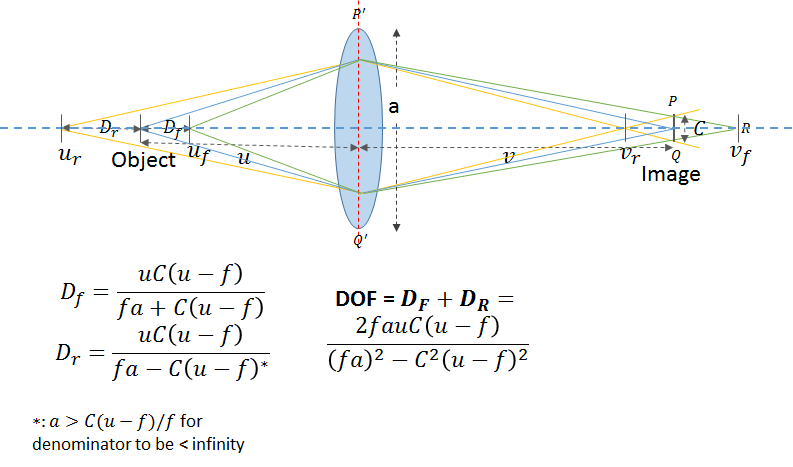
- Depth of Field: The concept of depth of field is closely related to the circle of confusion. The depth of field (DOF) is the range of distances between uf and ur, (Dr + Df ), where the circles of confusion, C is small enough so the image appears to be “in focus.”
The formulas for  and
and  shown above can be easily derived from the geometry of the figure (
 and
and  are similar triangles).
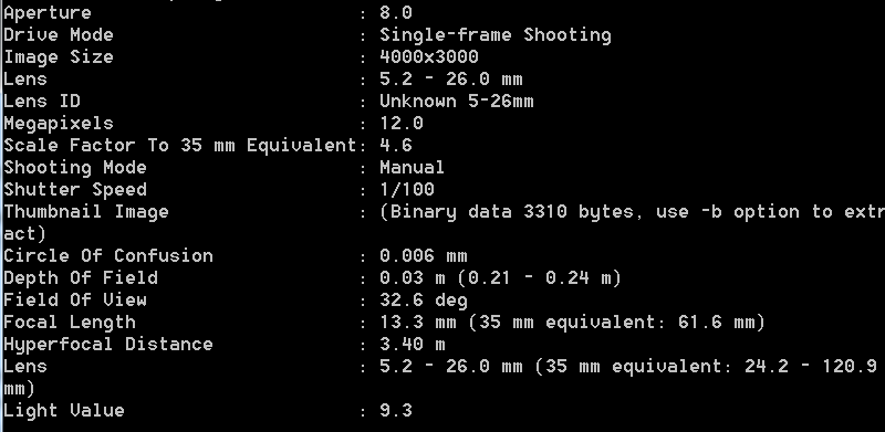
What is a good value of the circle of confusion for a digital camera? Let’s consider the Canon S100, an excellent GPS equipped 12MP camera with a 1/1.7″ sensor. I use this camera extensively for surveys.
| Sensor size | 1/1.7″ (7.44 x 5.58 mm) |
A reasonable way to define the circle of confusion for a digital camera is to set it equal to the distance between two pixels on the sensor. For the canon S100, distance between two pixels for a 4000 by 3000 px image is roughly 7.44/4000 = 0.002mm, therefore the circle of confusion is 0.004mm, since the circle of confusion is defined as the diameter of the circle. This value is quite close to the advertised value of the circle of confusion for the Canon S100, which is 0.006mm.
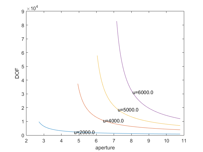
The formula for the depth of field shown above is quite complex, and the relationship between the focal length, aperture, object distance and the depth of field is not easy to discern. However, if we plot the depth of field versus aperture for a variety of focal lengths, we obtain the following graph (obtained using Matlab)
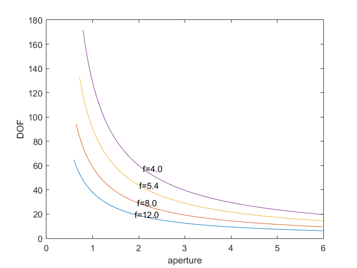
From this graph, we can see that as DOF is inversely proportional to the aperture, and also inversely proportional to the focal length. This observation is in accordance with the commonly held understanding of the relationship between DOF, aperture and the focal length.
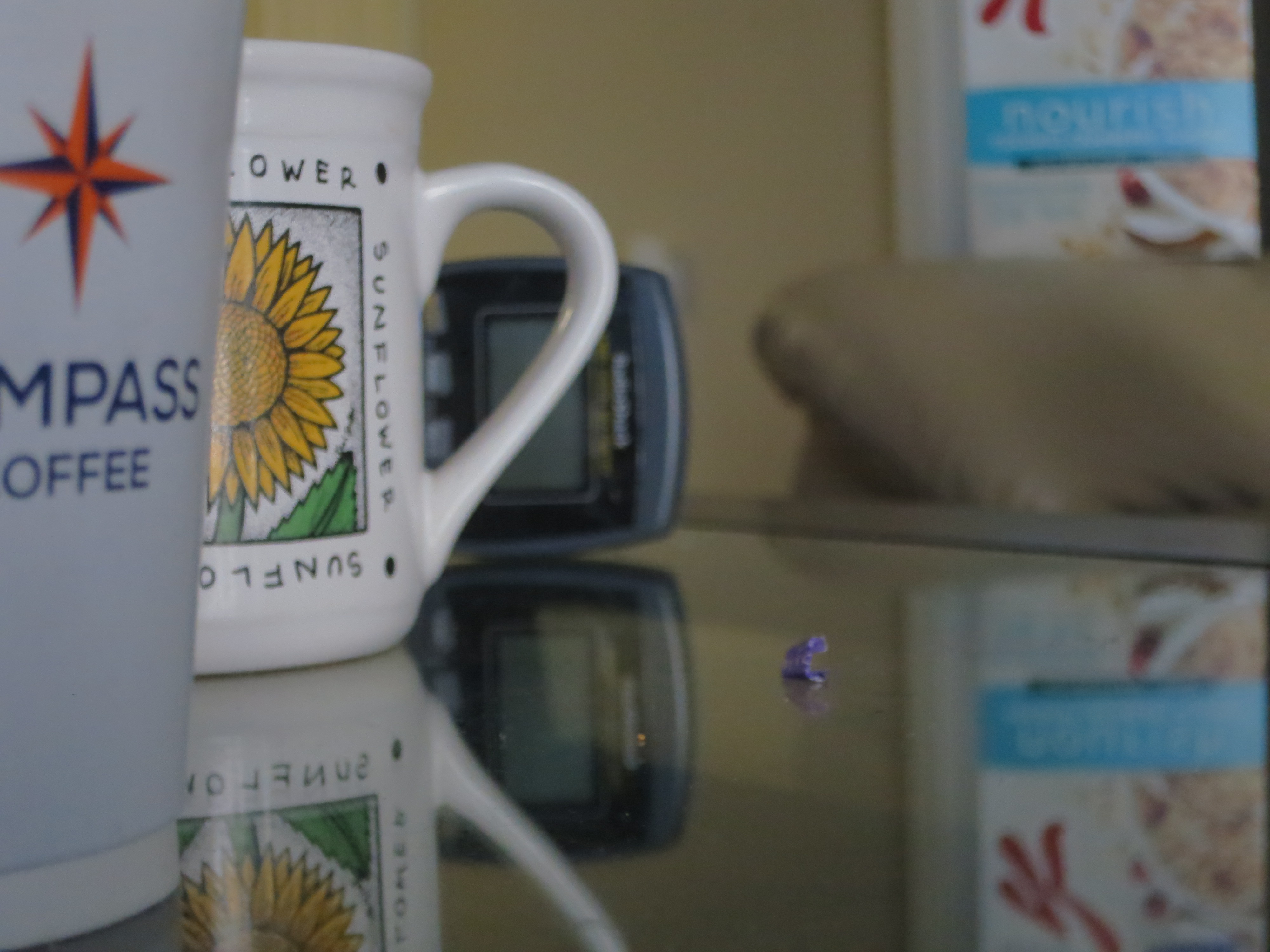
Let’s take a look at some real images now.

Changing Focus vs Changing Focal Length
Let’s digress a bit to understand the difference between changing the focus and changing the focal length. This might be obvious to some, but took me a bit to wrap my head around, so I think a discussion would be helpful. In the lens equation shown above, there are two parameters related to the camera that we can modify, the focal length f and v, the distance of the image plane from the camera center. When you change the zoom of the camera, you are modifying f. In most cameras, this is done mechanically by moving the lens elements to change the effective focal length.
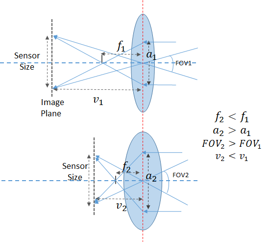
As shown in the figure above, decreasing the focal length increases the field of view (FOV) of the camera. For example, for a Canon S 100,
| f=13.3mm | FOV = 32.6 deg |
| f=5.2mm | FOV = 73.3 deg |
This is also easily borne out by simple math. From the figure above,  .
.
For cameras with a small focal length,  (consider for example, the value of
  for a camera with a focal length = 5.2mm focused on an object located 2m away. Applying the lens equation,
  , which is almost identical to
  ). Therefore for the Canon S100 with a sensor height of 7.44mm, the FOV comes out to be 71.16 deg for f = 5.2mm. This agrees well with the FOV value of 73.3 deg in the image exif tags.
Also note from the picture above that for a given sensor size, as the focal length increases, a smaller portion of the lens is exposed to the sensor. This is why as you zoom in (increase the lens focal length), the maximum allowed aperture value decreases.
So what happens when you change the lens focus? I’m not absolutely sure about this, but I suspect that this changes the by slightly moving the lens backward or forward with respect to the image sensor. Since for a camera with small focal length, the change required in for changes in  is very small, this doesn’t effect the calculations shown here.
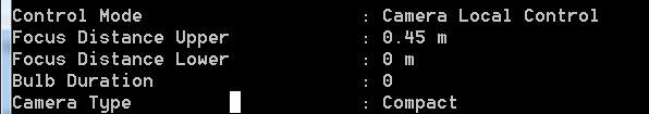
Incidentally, I have not found a way to read the focus distance anywhere in the image exif tags (for the Canon S100). The closest tag I found is called the “Focus Distance Upper” which appears to be set to a value about twice what I set as the manual focus distance.
DOF: Calculated Value vs. Value from Exif Tags
As a sanity check, I compared the value of the DOF obtained from the formula shown above with the values reported by the camera.
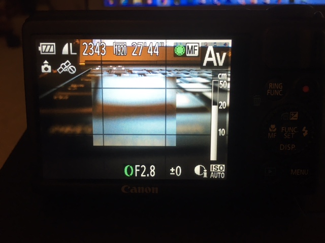
Consider the Canon S100 with f=13.3mm, aperture = f/8 focused on an object located 23 cm away. Applying the formulas shown above, we get = 12.7mm and = 14.4mm. Therefore the DOF =  = 27.1mm which agrees with the values contained in the exif tags.
Variation of DOF with Object Distance
Let’s now consider how the DOF changes as the camera focus is changed. In the previous section, we focused the camera to an object located about 20 cm away. While this scenario served well to illustrate the relationship between the DOF, focal length and aperture, it is not realistic for drone surveys where the camera is focused on a point much farther away.
 , approaches infinity (though stays finite), which would have made it impractical to plot the DOF. For drone survey purposes, is what matters, as there are typically no objects in between the drone and scene being surveyed. Therefore, we can conclude that once the object distance is higher than 6m, the field of view stops being a limiting factor for any reasonable focal length and aperture. One can safely set the aperture to whatever makes sense given the shutter speed and ISO. Note however that if you set the aperture too low, diffraction can start becoming an issue.In the next post, we’ll consider the issues of shutter speed and ISO and also look at how CHDK (Canon Hacker Development Kit) can be used to implement intervelometers that automatically adjust the camera settings to optimal values for survey purposes.
Great post on Aerial photography and Photogrammetry. I read both the parts of your article and it’s very detailed in pointing out the science behind the working of exposure, and the advantages and caveats of changing the three parameters that control the exposure. As a photographer, who also shoots time-lapses, I can definitely agree on the dynamic exposure settings, however, the difference is that from my point of view, I try to keep the exposure intact throughout the shoot while keeping a low shutter speed to capture motion blur of moving elements in the frame, whereas in your case, the motion is with the platform itself, hence your emphasis is on sharpness to capture non-blurry images.
Regarding your explanation of diffraction, I agree that shooting with a small apertures is not ideal as it introduces diffraction which in turn reduces sharpness, however, I have noticed that is not always the case with all megapixels. I could be wrong, but a smaller megapixel count on a sensor might not exhibit the same type of diffraction on a higher megapixel sensor (granted everything else remains the same).
Shutter speed is definitely important, however, from a moving platform, I believe you might get the “jello-effect” – that is the slight tilted-ness of objects captured because the shutter has to travel from one side to the other side of the sensor while it is in motion. Larger the sensor, the larger the effect, I believe. So the speed of the platform in addition to the shutter speed could be considered together, especially if you begin to shoot in video instead of individual images. Other alternative is probably to use a camera with a global-shutter.
Thanks for the article!